今天要介紹的是如何在Cadence上使用ADE ,完成雜訊模擬。
What I want to introduce today is how to use ADE on Cadence to complete
noise simulation.
以下圖模擬當例子,在R=1K,C=1pF情況下,輸出VO的電壓變化。
The following figure simulates an example, in the case of R=1K, C=1pF, the voltage
change of the output VO.
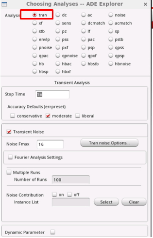
1.Open ADE XL/Maestro
First open the simulation environment, then open ADE XL or Maestro, select tran.
Noise Fmin=1/Ts。
因此可以知道,模擬時間太短是無法反映出電路本身的Flicker Noise。
一般電路使用moderate是很夠用的,除非你電路是高解析的ADC/DAC。
Moderate is sufficient for general circuits, unless your circuit is a high-resolution
Simulation time has nothing to do with how low frequencies we want Noise to see.
Noise Fmin=1/Ts.
Therefore, it can be known that the simulation time is too short to reflect the Flicker Noise
of the circuit itself.
3.Set Simulation Accuracy
Moderate is sufficient for general circuits, unless your circuit is a high-resolution
ADC/DAC.
當然這邊值大到一定程度,其實影響電路就很細微了,讀者可以自己嘗試看看自己電
路的邊界在哪邊。
Readers here can try it out for themselves. The larger the value here, the closer to the actual
situation.
Of course, the value here is large to a certain extent, in fact, the impact on the circuit is very
subtle. Readers can try to see where the boundary of their own circuit is.
是Noise Fmin還是被1/Ts決定。
Here you can provide another option for setting Fmin, but it should be noted that even if
you play 1Hz here, the Noise Fmin is still determined by 1/Ts.
公式Vo Noise rms=(KT/C)^0.5=64uVrms,模擬值為56Vrms
這邊跟手算有誤差原因,是我Noise Fmax設定不夠大,當Fmax夠大的時候會接近手
算的值!(可是相對模擬速度會慢很多)
As you can see the simulation results, VO changes as expected.
The formula Vo Noise rms=(KT/C)^0.5=64uVrms, the analog value is 56Vrms
The reason for the error here is that my Noise Fmax setting is not large enough. When
Fmax is large enough, it will be close to the hand.
Calculated value! (But the relative simulation speed will be much slower)
以上,有興趣的朋友可以實做看看!
大家如果有疑問歡迎提出,或者有其他方式也歡迎拿出來討論。
The above, interested friends can actually do it!
If you have any questions, you are welcome to raise them, or you are welcome to discuss
them in other ways.


多教一點拜託QQ
回覆刪除白天是工程師比較忙,更新只能隨緣了QQ
刪除請問transient中的noise fmin 和noise fmax
回覆刪除noise的運算方式是從fmin積分到fmax嗎
謝謝
是的,概念跟.noise模擬是滿相近的(.noise 的模擬確實下限和上限是積分範圍)
刪除請問你知道pll設計中的phase noise嗎
刪除他也是分段頻率做積分的概念 然後再將個頻率積分後的結果
做均方根值運算轉換成jitter
剛您回覆transient noise也是積分的概念
只是不知道他是否也是像phase noise那樣分段積分
那運算後的結果會與phsae noise差不多嗎
謝謝
phase noise,我比較不熟,但之前有聽我同事分享過
刪除理論上phase noise 或 tran noise 或 dc .noise 應該都要得掉到一樣結果
您好,我想請教一下兩個問題
回覆刪除第一,最後一張的紅色長條圖 你是怎麼叫出來的
第二,你有用過.noise 去模擬過 出來的結果要怎麼去跟transient noise 去對照
謝謝您
1.tool 裡面應該有個histgram喔
刪除2.noise(選好積分範圍,然後單位選RMS)=>出來結果就是rms noise
transient noise跑完,先把平均值減掉,然後對她做RMS(STD)運算
理論上得到的結果會一致